Most national instruments stepper motor. Stepper motors with these center taps are often referred to as unipolar motors. The motor will supply the same amount of power but with a different load amperage. Six wire three phase electric motors are dual voltage motors. What we need to do is measure the resistance from one motor wire to another. If the single pole switch marked s1 is left open then the liquid level switch in the circuit will now be the control device that turns the motor starter on or off. The two wire circuit in configuration 2 operates as follows. How the wires are interconnected dictates the voltage being supplied to the motor. If the single pole switch is toggle closed the motor starter will start and stay on for as long as the single pole switch is closed. This motor uses six wires.
The two wire circuit in configuration 2 operates as follows. If the single pole switch marked s1 is left open then the liquid level switch in the circuit will now be the control device that turns the motor starter on or off. Each of the two coils. Please help how to go about this. Single speed motors for delta wired motors for star wired motors diagram dd1 diagram dd2 suggested wiring arrangement u1 u1 v1 v1 w1 w1 u2 u2 v2 v2 w2 w2 l1 l1 l2 l2 l3 l3 e e two speed motors with 2 separate windings dual winding high speed red leads red leads black leads black leads m 3 single speed only 3ø wiring diagrams u1 red v1 yellow w1 blue black thermal contacts tb. What we need to do is measure the resistance from one motor wire to another. The supply voltage is either 240 volts alternating current vac or 480 vac. One contactor burnt for high speed and a replced contactor does not engange originally the coils re fed with a nutural and the one i replaced is only working with a phase. Most stepper motors come with four six or eight wires. Stepper motors with these center taps are often referred to as unipolar motors.
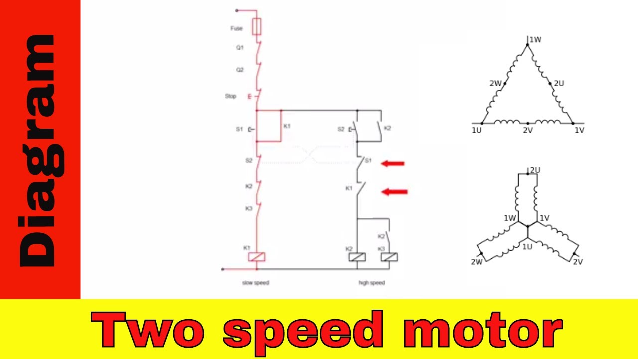
Most national instruments stepper motor. This is achieved by altering the wiring connections inside the motor the motor may have fixed or variable torque depending on the stator winding. Each of the two coils. A dahlander motor also known as a pole changing motor dual or two speed motor is a type of multispeed induction motor in which the speed of the motor is varied by altering the number of poles. Six wire three phase electric motors are dual voltage motors. If the single pole switch marked s1 is left open then the liquid level switch in the circuit will now be the control device that turns the motor starter on or off. This is because of the way stepper motors are made stepper motors will have two coils and since this motor has six wires that means there are 3 wires per coil. Kindly email me the diagrams for star deltor and direct online for a 3speed 1directon 3ph motor have two of them in a bow cutter. What we need to do is measure the resistance from one motor wire to another. One contactor burnt for high speed and a replced contactor does not engange originally the coils re fed with a nutural and the one i replaced is only working with a phase.
The motor will supply the same amount of power but with a different load amperage. If the single pole switch marked s1 is left open then the liquid level switch in the circuit will now be the control device that turns the motor starter on or off. This is because of the way stepper motors are made stepper motors will have two coils and since this motor has six wires that means there are 3 wires per coil. Six wire three phase electric motors are dual voltage motors. Stepper motors with these center taps are often referred to as unipolar motors. This motor uses six wires. Most national instruments stepper motor. A dahlander motor also known as a pole changing motor dual or two speed motor is a type of multispeed induction motor in which the speed of the motor is varied by altering the number of poles. Single speed motors for delta wired motors for star wired motors diagram dd1 diagram dd2 suggested wiring arrangement u1 u1 v1 v1 w1 w1 u2 u2 v2 v2 w2 w2 l1 l1 l2 l2 l3 l3 e e two speed motors with 2 separate windings dual winding high speed red leads red leads black leads black leads m 3 single speed only 3ø wiring diagrams u1 red v1 yellow w1 blue black thermal contacts tb. Please help how to go about this.
Stepper motors with these center taps are often referred to as unipolar motors. The two wire circuit in configuration 2 operates as follows. Each of the two coils. The motor will supply the same amount of power but with a different load amperage. A 6 wire stepper motor is similar to a 4 wire configuration with the added feature of a common tap placed between either end of each phase as shown in figure 2. This wiring configuration is best suited for applications requiring high torque at relatively low speeds. One contactor burnt for high speed and a replced contactor does not engange originally the coils re fed with a nutural and the one i replaced is only working with a phase. Most stepper motors come with four six or eight wires. How the wires are interconnected dictates the voltage being supplied to the motor. Single speed motors for delta wired motors for star wired motors diagram dd1 diagram dd2 suggested wiring arrangement u1 u1 v1 v1 w1 w1 u2 u2 v2 v2 w2 w2 l1 l1 l2 l2 l3 l3 e e two speed motors with 2 separate windings dual winding high speed red leads red leads black leads black leads m 3 single speed only 3ø wiring diagrams u1 red v1 yellow w1 blue black thermal contacts tb.